In my earlier blog on L2VPN via CCC https://networkzblogger.com/2017/04/23/l2vpn-via-ccc-in-junos/ we saw in that method customer interface needs to be bind with LSP and for each customer we need to have separate LSP configured which is not ideal from operational perspective. In this blog we will look at another method of achieving this where BGP is used as signalling protocol which automates the connections, so manual configuration of the association between the LSP and the customer edge interface is not required.
This config is also called Kompella after its author (https://tools.ietf.org/html/draft-kompella-l2vpn-l2vpn-00) where BGP is used to signal the control plane and it uses a two label stack as Martini. The VC (VPN) label is signalled via BGP and transport label can be signaled via either RSVP or LDP.
We would be looking at below topology where we will be configuring the MPLS L2VPN or Juniper L2CIRCUIT between M10i and MX960 PEs. M320s in between are just acting as Transit P/PE nodes and no configuration specifically needed on them for L2VPN however normal RSVP/LDP/MPLS/IGP config needs to be configured for transport label same as how L3VPN works.
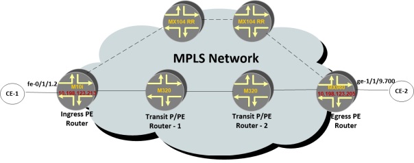
MX104s are acting as RR so BGP neighborship will appropriate family needs to be activated between PEs-RRs.
For BGP based L2VPNs, following configuration needs to be configured
- BGP group with family l2vpn signalling
- Routing instance using instance type “l2vpn”
- Ethernet link needs to be established with Customer and same needs to be defined under Routing-instance.
Let’s start with Juniper l2vpn configuration.
First BGP Group where l2vpn signalling family needs to be enabled for PE-RR group.
BGP neighborship between M10i and one of the RR.
M10i-PE> show configuration protocols bgp group L2VPN-RRs
type internal;
family l2vpn {
    signaling;
}
authentication-algorithm md5;
authentication-key-chain BGP-L2VPN-key-chain;
neighbor 10.198.123.234;  <<<<<<<<< Loopback of RR1
neighbor 10.198.123.237;  <<<<<<<<< Loopback of RR2
BGP neighborship between M10i and one of the RR.
M10i-PE > show bgp neighbor 10.198.123.234
Peer: 10.198.123.234+179 AS 65004 Local: 10.198.123.213+50453 AS 65004
 Group: L2VPN-RRs Routing-Instance: master
 Type: Internal State: Established Flags: <Sync>
 Options: <Preference LocalAddress GracefulRestart LogUpDown AddressFamily Rib-group Refresh>
 Address families configured: l2vpn-signaling
 Local Address: 10.198.123.213 Holdtime: 90 Preference: 170
 Peer ID: 10.198.123.234 Local ID: 10.198.123.213 Active Holdtime: 90
 NLRI for restart configured on peer: l2vpn
 NLRI advertised by peer: l2vpn
 NLRI for this session: l2vpn
 Peer supports Refresh capability (2)
 Restart time configured on the peer: 120
 Stale routes from peer are kept for: 300
 Restart time requested by this peer: 120
 NLRI that peer supports restart for: l2vpn
 NLRI peer can save forwarding state: l2vpn
 NLRI that peer saved forwarding for: l2vpn
 NLRI that restart is negotiated for: l2vpn
 NLRI of received end-of-rib markers: l2vpn
 NLRI of all end-of-rib markers sent: l2vpn.
.
.
Even though customer facing config is not part of MPLS L2VPN, I will define it here which is using l2vpn encapsulation vlan-ccc.
M10i-PE > show configuration interfaces fe-0/1/1
description "Connected to CE-1";
vlan-tagging;
link-mode full-duplex;
encapsulation vlan-ccc;
unit 2 {
 encapsulation vlan-ccc;
 vlan-id 1001;
 family ccc;
}
Fairly simple configuration which is using encapsulation vlan-ccc.
OK, lets move to 2nd and 3rd part which is routing-instance configuration. I have highlighted important bits below. Off course for this L2VPN type you need to define RD, RT, and Interface which I am not mentioning specifically but you can see below.
M10i-PE > show configuration routing-instances L2VPN
instance-type l2vpn;
interface fe-0/1/1.2;
route-distinguisher 10.198.123.213:2;
vrf-target target:65004:2;
protocols {
 l2vpn {
 encapsulation-type ethernet-vlan;
 site Audi {
 site-identifier 2;
 interface fe-0/1/1.2 {
 remote-site-id 3;
 }
 }
 }
}
Important bit is instance-type l2vpn which enables this routing-instance for L2VPN. Under protocols l2vpn we have to enable the encap type as ethernet-vlan and then under site parameters we need to be define local site-identifier which is in our case is 2 and an optional remote-site-id. I have defined remote-site-id as 3 which will be configured on MX960 Remote-PE as its local site-identifier.
In same way we will be configuring the MX960 PE
MX960-PE> show configuration interfaces ge-1/1/9.700
encapsulation vlan-ccc;
vlan-id 700;
family ccc;

MX960-PE> show configuration routing-instances L2VPN
instance-type l2vpn;
interface ge-1/1/9.700;
route-distinguisher 10.198.123.205:3;
vrf-target target:65004:2;
protocols {
 l2vpn {
 encapsulation-type ethernet-vlan;
 site Bentley {
 site-identifier 3;
 interface ge-1/1/9.700 {
 remote-site-id 2;
 }
 }
 }
}
Once this is configured, let’s check the routing table on M10i
M10i-PE > show route table L2VPN.l2vpn.0
L2VPN.l2vpn.0: 3 destinations, 5 routes (3 active, 0 holddown, 0 hidden)
Restart Complete
+ = Active Route, - = Last Active, * = Both

10.198.123.205:3:3:1/96 <<<<<<<<<------------ Learnt from MX960
 *[BGP/170] 13:56:58, localpref 100, from 10.198.123.237
 AS path: I, validation-state: unverified
 > via so-0/0/0.0, Push 299888
 [BGP/170] 13:56:58, localpref 100, from 10.198.123.234
 AS path: I, validation-state: unverified
 > via so-0/0/0.0, Push 299888
.
.
.
10.198.123.213:2:2:3/96 <<<<<<<<-------------- Local route on M10i
 *[L2VPN/170/-101] 16:56:08, metric2 1
 Indirect
This output is showing us RD value of 10.198.123.205:3 plus value of remote-side identifier which is 3 as well plus label-offset value which is 1
In same way, local route has RD value of 10.198.123.213:2 plus value of remote-side identifier which is 2 and label-offset value of 3. Will explain label-offset later.
So this completes our BGP control signalling path.
L2VPN connection state is up between both PEs
M10i-PE > show l2vpn connections up
Layer-2 VPN connections:

Instance: L2VPN
Edge protection: Not-Primary
 Local site: Audi (2)
 connection-site Type St Time last up # Up trans
 3               rmt  Up May 2 20:53:51 2017 1
 Remote PE: 10.198.123.205, Negotiated control-word: Yes (Null)
 Incoming label: 800006, Outgoing label: 800003
 Local interface: fe-0/1/1.2, Status: Up, Encapsulation: VLAN
Now we can move over to forwarding path where we will see MPLS labels. As in case of L3VPNs, we have 2 Labels on each packet i.e. VPN Label and other is transport label.
Transport label is calculated in same way where label is assigned for next-hop which in our case is remote-PE MX960 loopback address and this label can be learnt by any method LDP or RSVP and will be advertised to M10i PE by its immediate neighbour which in our case is M320.
So to check the label stack which is being pushed at M10i, we can see the MPLS.0 table.
M10i-PE > show route table mpls.0
mpls.0: 25 destinations, 25 routes (25 active, 0 holddown, 0 hidden)
Restart Complete
+ = Active Route, - = Last Active, * = Both
.
.
.
fe-0/1/1.2 *[L2VPN/7] 14:27:18, metric2 1
 > via so-0/0/0.0, Push 800003, Push 299888(top) Offset: 252
So you can see two labels are being pushed, TOP (transport) label is 299888 which is advertised by M320
M320-Transit-P-1> show ldp database session 10.198.123.213
.
.

Output label database, 10.198.123.202:0--10.198.123.213:0
 Label Prefix
 306336 10.198.123.100/32
 299808 10.198.123.201/32
 3      10.198.123.202/32
 299792 10.198.123.203/32
 308832 10.198.123.204/32
 299888 10.198.123.205/32
 304288 10.198.123.211/32
VPN Label is 800003 which is calculated little bit differently in case of L2VPNs and not directly advertised by Remote-Pes.
Formula to calculate VPN label is
L2VPN label = Label-Base (remote) + Site-Id(Local) – Label-Offset (remote)
Label-base (remote) value is what we can get from MX960 by looking at its L2VPN.l2vpn table
MX960-PE > show route table L2VPN.l2vpn.0 extensive
L2VPN.l2vpn.0: 3 destinations, 5 routes (3 active, 0 holddown, 0 hidden)
.
.
 Advertised metrics:
 Flags: Nexthop Change
 Nexthop: Self
 Localpref: 100
 AS path: [65004] I
Path 10.198.123.205:3:3:1 Vector len 4. Val: 0
 *L2VPN Preference: 170/-101
 Next hop type: Indirect, Next hop index: 0
 Address: 0xa5d246c
.
.
.
 Label-base: 800002, range: 2, status-vector: 0x0, offset: 1
 Secondary Tables: L2VPN.l2id.0
You can see above that label-base is 800002 on MX960 and Label-offset value is 1
So as per our equation above,
L2VPN Label = 800002 + 2 (Site-id local on M10i) – 1 = 800003
Once this VPN Label reaches MX960, it is pop as per normal MPLS procedures and out to CE-2 interface.
800003 *[L2VPN/7] 14:37:16
 > via ge-1/1/9.700, Pop Offset: 4
In same way, MX960 will also calculate the VPN label for traffic flowing from MX960 to M10i.
So that’s all for this blog. I hope you enjoyed it and let me know if you still have any issues.
Regards
Mohit Mittal

thank you , it helped a lot
LikeLike
Hi.. Great work, thank you . I am new in juniper world, what does it mean when the pe to ce encapsulation 700, does it mean connecting customer vlan 700 in both site and what is the ce to pe interface configuration look like ?
Thank you in advance.
Basem
LikeLike