vSONIC Virtual Switch on EVE-NG

SONiC is an open source network operating system based on Linux that runs on switches from multiple vendors and ASICs. SONiC offers a full-suite of network functionality, like BGP and OSPF, VXLAN that has been production-hardened in the data centers of some of the largest cloud-service providers.

The community around SONiC has been growing and includes Juniper including Apstra, Arista, Nokia, Alibaba, Comcast, Cisco, Broadcom, Nvidia-Mellanox and VMware. SONiC underpins Microsoft’s Azure networking services. According to IDC, a SONiC data-center switch market will be worth $2 billion by 2024.

Some term it as ‘Linux of Networking’.

In this blog, we will see how to spin up a sample topology using vSONIC Virtual Switch on EVE-NG.

To start with, we will use mssonic.yml file which lists the generic parameters for spinning up the instance.

  1. Copy mssonic.yml file into “/opt/unetlab/html/templates/intel” or “/opt/unetlab/html/templates/amd” based on your cpu. In my case, I am using EVE-NG on macbook so I have used Intel.

root@eve-ng:~# ls -l /opt/unetlab/html/templates/intel/ | grep mssonic

-rw-r–r– 1 root root 1993 Jul 30 22:41 mssonic.yml

root@eve-ng:~#

2. Create a folder under “opt/unetlab/addons/qemu/” with name “mssonic-version/” like “mssonic-3.1.2”.

Keyword “mssonic” is important as using this only, eve-ng will recognize this image.

root@eve-ng:~# ls -l /opt/unetlab/addons/qemu/ | grep ms

drwxr-xr-x 2 root root 4096 Jul 30 22:48 mssonic-3.1.2

root@eve-ng:~#

https://github.com/Broadcom/sonic-VirtualSwitch/tree/master/3.1.2

3. Gunzip the .gz file to extract the image file.

root@eve-ng:/opt/unetlab/addons/qemu/mssonic-3.1.2# gunzip sonic-vs-3.1.2.img.gz

root@eve-ng:/opt/unetlab/addons/qemu/mssonic-3.1.2# ls -l

total 2380932

-rw-r–r– 1 root root 2438070272 Jul 30 22:55 sonic-vs-3.1.2.img

4. Rename sonic-vs-3.1.2.img to virtioa.qcow2. Please make sure to rename only and don’t convert it.

root@eve-ng:/opt/unetlab/addons/qemu/mssonic-3.1.2# mv sonic-vs-3.1.2.img virtioa.qcow2

root@eve-ng:/opt/unetlab/addons/qemu/mssonic-3.1.2# ls -l

total 2380932

-rw-r–r– 1 root root 2438070272 Jul 30 22:58 virtioa.qcow2

5. Fix the permissions as usual on eve-ng.

root@eve-ng:/opt/unetlab/addons/qemu/mssonic-3.1.2# /opt/unetlab/wrappers/unl_wrapper -a fixpermissions

root@eve-ng:/opt/unetlab/addons/qemu/mssonic-3.1.2#

Now we all set to use this under EVE-NG

I have made a simple leaf-spine topology using Sonic Virtual Switches

6. Open the Eve-NG UI.

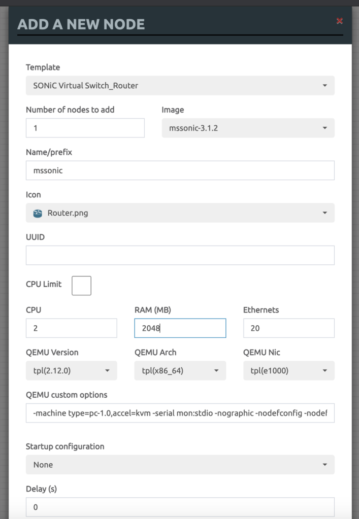
Add the new Node, and select Sonic Router as below.

7. Change any settings here if you need however defaults should be good.

8. I have built a simple Leaf-Spine topology using 4 Sonic VS.

9. Start one or more Switches and let it boot.

Trying 172.16.137.130…

Connected to 172.16.137.130.

Escape character is ‘^]’.

Jul 31 15:30:59.295935 2021 sonic INFO sonic-ztp[3850]: ZTP service started.

Jul 31 15:30:59.295971 2021 sonic INFO sonic-ztp[3850]: Failed to set system MAC address as the random number generator seed input.

Jul 31 15:30:59.295999 2021 sonic INFO sonic-ztp[3850]: Checking running configuration to load ZTP configuration profile.

Jul 31 15:30:59.893505 2021 sonic INFO sonic-ztp[3845]: Waiting for system online status before continuing ZTP. (This may take 30–120 seconds).

Debian GNU/Linux 9 sonic ttyS0

Jul 31 15:31:34.932822 System is ready

Jul 31 15:31:36.290136 2021 sonic INFO sonic-ztp[3845]: System is ready to respond.

Jul 31 15:31:36.308466 2021 sonic INFO sonic-ztp[3850]: Link up detected for interface Ethernet0

Jul 31 15:31:36.308525 2021 sonic INFO sonic-ztp[3850]: Link up detected for interface Ethernet1

Jul 31 15:31:36.308554 2021 sonic INFO sonic-ztp[3850]: Link up detected for interface Ethernet2

Jul 31 15:31:36.308581 2021 sonic INFO sonic-ztp[3850]: Link up detected for interface Ethernet3

Jul 31 15:31:36.308609 2021 sonic INFO sonic-ztp[3850]: Link up detected for interface Ethernet4

Jul 31 15:31:36.308637 2021 sonic INFO sonic-ztp[3850]: Link up detected for interface Ethernet5

Jul 31 15:31:36.308664 2021 sonic INFO sonic-ztp[3850]: Link up detected for interface Ethernet6

Jul 31 15:31:36.308741 2021 sonic INFO sonic-ztp[3850]: Link up detected for interface Ethernet7

Jul 31 15:31:36.308769 2021 sonic INFO sonic-ztp[3850]: Link up detected for interface Ethernet8

Jul 31 15:31:36.308821 2021 sonic INFO sonic-ztp[3850]: Link up detected for interface Ethernet9

Jul 31 15:31:36.308850 2021 sonic INFO sonic-ztp[3850]: Link up detected for interface Ethernet10

Jul 31 15:31:36.309163 2021 sonic INFO sonic-ztp[3850]: Link up detected for interface Ethernet11

Jul 31 15:31:36.340452 2021 sonic INFO sonic-ztp[3850]: Link up detected for interface Ethernet12

Jul 31 15:31:36.340489 2021 sonic INFO sonic-ztp[3850]: Link up detected for interface Ethernet13

Jul 31 15:31:36.340761 2021 sonic INFO sonic-ztp[3850]: Link up detected for interface Ethernet14

Default username/pwd – admin/YourPaSsWoRd

10. Once up and running, you would see lots of ztp related messages which can be disabled using below command.

sudo config ztp disable

sudo config save -y

11. Once done, you can go into sonic cli, using sonic-cli

admin@sonic:~$ sonic-cli

sonic#

sonic#

sonic# ?

  clear        Clear commands

  configure    Enter configuration mode

  copy         Perform file copy operations

  exit         Exit from the CLI

  fast-reboot  fast-reboot [options] (-h shows help)

  image        Image related commands

  logger       Enter messages into the system log

  no           No commands under Exec mode

  ping         Send ICMP ECHO_REQUEST to network hosts

  ping6        Send ICMPv6 ECHO_REQUEST to network hosts

  reboot       reboot [options] (-h shows help)

  renew        Renew commands

  show         Show running system information

  terminal     Set terminal settings

  tpcm         SONiC image installation manager

  traceroute   Print the route packets take to the host

  traceroute6  Print the route packets take to the IPv6 host

  warm-reboot  warm-reboot [options] (-h shows help)

  write        Save config

sonic#

to prove its working, lets configure IP Addresses on Interfaces and see if we can ping each other.

On Leaf-1:

sonic(config)# hostname leaf-1

leaf-1#

leaf-1#

leaf-1#

leaf-1#

leaf-1# show running-configuration interface Ethernet 0

!

interface Ethernet0

 mtu 9100

 speed 25000

 fec none

 no shutdown

 ip address 10.10.10.2/30

leaf-1#

On Spine-1:

spine-1# show running-configuration interface Ethernet0

!

interface Ethernet0

 mtu 9100

 speed 25000

 fec none

 no shutdown

 ip address 10.10.10.1/30

spine-1#

12. Ping the other end to find everything is working

spine-1# ping 10.10.10.2

PING 10.10.10.2 (10.10.10.2) 56(84) bytes of data.

64 bytes from 10.10.10.2: icmp_seq=1 ttl=64 time=5.32 ms

64 bytes from 10.10.10.2: icmp_seq=2 ttl=64 time=1.34 ms

^C

— 10.10.10.2 ping statistics —

2 packets transmitted, 2 received, 0% packet loss, time 1001ms

rtt min/avg/max/mdev = 1.349/3.336/5.323/1.987 ms

spine-1#

That’s all, hope you like it.. In next sessions, we can go through some more specific scenarios around it.

Service Assurance with Juniper Paragon Active Assurance (Netrounds)

Hi All, hope you all are well.

In this blog, will look at Juniper’s recent acquisition called Netrounds. Netrounds have been rebranded as Paragon Active Assurance (PAA) which is part of Paragon Automation portfolio and is a programmable, active test and monitoring solution for physical, hybrid, and virtual networks. Unlike passive monitoring approaches, Paragon Active Assurance uses active, synthetic traffic to verify application and service performance at the time of service delivery and throughout the life of the service.

There are various features of PAA however in nutshell, operations teams can use PAA to identify, understand, troubleshoot, and resolve issues before your end users even notice them. This service performance visibility can help decrease incident resolution time by as much as 50%, resulting in greater end-user satisfaction and retention.

We will be using simple topology consisting of a Controller, Test Agents and 2 vMXs to model it in EVE-NG.

eve-ng netrounds juniper active assurance
EVE-NG Topology

Controller has been instantiated by spinning clean Ubuntu 18.04.05 LTS VM and then added the required controller packages.
 
You can get the Controller up and running by following the below URL:
 
https://www.juniper.net/documentation/us/en/software/active-assurance3.0.0/paa-install/topics/concept/install-os-software.html
 
Controller Version: 3.0.0
vMX version: 18.2R2-S4
Test Agent: 3.0.0.23

Once the controller is up and running and has been licensed, you can open the UI page on the its management address.

In my case its on https://192.168.8.113/ and you will be presented with login screen where after getting authenticated, you will land on Dashboard page.

For us, as expected nothing is here as no configuration has been added via UI.

Once controllers are up, we will add Test Agents (TA) to manage all from single pane of glass.

We will add 2 TAs, and for that we need to build new Linux VM however this time its all prepackaged VM in .qcow2 format which we can download from Controller UI.

Download the .qcow2 format, disk image.

Once downloaded, we will boot the VM using this Qemu image and will get the Test Agent up and running. Now we need to open console to TEST Agent and add the Controller IP in format: <controller-ip>:6000

6000 is important as TA and Controller talk on this port. If you have firewall in between, make sure to allow this port.

Once both TAs are added, they will be shown in the Test Agents Section on the left menu of the Controller as below.

Click on each Test Agent and configure the IP Addresses on Revenue port. In my case its eth1 which is connected to vMXs.

Before we delve more into TAs, let me give you run down of vMXs.

vMXs have OSPF, LDP, RSVP, BGP, running between them. I have configured L2VPN CCC between 2 VMXs.

As you can see below, interface towards TA1 is in vlan 601 and hence we need to accordingly add 601 vlan on TA1 and assign the IP. In my case, I have defined 20.20.20.1/24.

root@vMX-1> show mpls lsp
Ingress LSP: 1 sessions
To From State Rt P ActivePath LSPname
2.2.2.2 1.1.1.1 Up 0 * vmx1-to-vmx2
Total 1 displayed, Up 1, Down 0

Egress LSP: 1 sessions
To From State Rt Style Labelin Labelout LSPname
1.1.1.1 2.2.2.2 Up 0 1 FF 299808 - vmx2-to-vmx1
Total 1 displayed, Up 1, Down 0

Transit LSP: 0 sessions
Total 0 displayed, Up 0, Down 0

root@vMX-1> show connections
CCC and TCC connections [Link Monitoring On]
Legend for status (St): Legend for connection types:
UN -- uninitialized if-sw: interface switching
NP -- not present rmt-if: remote interface switching
WE -- wrong encapsulation lsp-sw: LSP switching
DS -- disabled tx-p2mp-sw: transmit P2MP switching
Dn -- down rx-p2mp-sw: receive P2MP switching
-> -- only outbound conn is up Legend for circuit types:
<- -- only inbound conn is up intf -- interface
Up -- operational oif -- outgoing interface
RmtDn -- remote CCC down tlsp -- transmit LSP
Restart -- restarting rlsp -- receive LSP

Connection/Circuit Type St Time last up # Up trans
l2vpn-1 rmt-if Up Mar 5 13:02:14 2
ge-0/0/1.601 intf Up
vmx1-to-vmx2 tlsp Up
vmx2-to-vmx1 rlsp Up

Another important consideration to make is NTP. Make sure NTP is synced properly on TAs before running the test. You can use any NTP server for this or make your controller as NTP server.

That’s all for vMXs, let me know if you have any particular query on it. We will look at TAs now.

To start the test, Click on ‘New Monitor’ under Monitoring option on left hand menu.

Fill the details and select Element. In our case we have selected 2 Elements, UDP and VOIP UDP which are basically 2 different streams with 2 different profiles going at same time.

Configure each element separately with parameters and Client and Server interface ports.

You can define the threshholds here and frame rates, dscp value of streams.

Press the start button. Once started, we can verify the traffic on vMXs in both Input and Output direction below which suggests that bidirectional traffic is working.


root@vMX-1> show interfaces ge-0/0/1 | match rate | refresh 1

---(refreshed at 2021-03-05 13:22:05 UTC)---

  Input rate     : 185792 bps (59 pps)

  Output rate    : 185792 bps (59 pps)

    FEC Corrected Errors Rate               0

    FEC Uncorrected Errors Rate             0

---(refreshed at 2021-03-05 13:22:06 UTC)---

  Input rate     : 185792 bps (59 pps)

  Output rate    : 185792 bps (59 pps)

    FEC Corrected Errors Rate               0

    FEC Uncorrected Errors Rate             0

---(refreshed at 2021-03-05 13:22:07 UTC)---

  Input rate     : 188064 bps (59 pps)

  Output rate    : 188064 bps (59 pps)

    FEC Corrected Errors Rate               0

    FEC Uncorrected Errors Rate             0

---(refreshed at 2021-03-05 13:22:08 UTC)---

  Input rate     : 188064 bps (59 pps)

  Output rate    : 188064 bps (59 pps)

    FEC Corrected Errors Rate               0

    FEC Uncorrected Errors Rate             0

---(refreshed at 2021-03-05 13:22:09 UTC)---

  Input rate     : 187680 bps (59 pps)

  Output rate    : 187680 bps (59 pps)

    FEC Corrected Errors Rate               0

    FEC Uncorrected Errors Rate             0

---(refreshed at 2021-03-05 13:22:10 UTC)---

  Input rate     : 187680 bps (59 pps)

  Output rate    : 187680 bps (59 pps)

    FEC Corrected Errors Rate               0

    FEC Uncorrected Errors Rate             0

---(refreshed at 2021-03-05 13:22:11 UTC)---

Once stopped. Click on the report at the top and you will get the status of test along with results and graphs.

That’s all from this blog. Its just an introduction to PAA however its capable of doing much much more. We can use the RPM/TWAMP on Routers to get the 2 way or Round trip time measurements from the network which can give you edge before handing over the network to your customers for actual traffic and proactively troubleshoot for any issues.

That’s all for this. I will add more test in next blogs, however till then let me know if you have any queries.

Mohit

Juniper Config Backup on GITLAB

Hi All

In this blog, we will see how we can take the backup of router configs and push it to gitlab for version control.

We will take Juniper routers here for example and build the script in Python and run our task as a cronjob on CentOS 7 to automatically backup the configs onto GITLAB.
We will use power of Git here to store the differentials in configs and we can see the differences in Gitlab UI.

So let’s see how we can achieve it.
Before starting with config backup, let’s build the device store on which we will be running the script or in other words backup will be running. For this we are storing the values in YAML file http://yaml.org/ as dictionary. You can either store the values as list or Dictionary in YAML. You can use json also to store the same data instead of YAML.

Yaml file (.yml)
---
# Add devices here in form Hostname: 'ip address'
  Manchester_MX10003: '10.198.206.3'
  Glasgow_MX10003: '10.198.206.6'
  London_MX104: '10.198.206.9'
  Leeds_MX104: '10.198.206.12'
  Bristol_MX104: '10.198.206.15'

Above are the file contents, where we are storing the data as Key, Value pair where Key is hostname of device and Values are its IP Addresses.

Now our data store is done, we can start with Juniper PYez (https://www.juniper.net/documentation/en_US/junos-pyez/topics/concept/junos-pyez-overview.html) to get the configs first.

We will be importing the Pyez modules, set the .yml input file location and run ‘for’ loop on our dictionary. We will store the backup config files as .txt file with hostnames as Title for easy accessibility. Don’t forget to import yaml module as we will be working on yaml file.

from jnpr.junos import Device
from jnpr.junos.exception import ConnectError
import yaml

input_file = '/home/sun/gitlab/device_list.yml'

for key, value in yaml.load(open(input_file)).items():

    dev_username = test
    dev_password = test
    dev = Device(host=value, user=dev_username, passwd=dev_password, port='830')

    try:
        dev.open()
    except ConnectError as err:
        print ("Cannot connect to device: {0}".format(err))
        sys.exit(1)
    except Exception as err:
        print (err)
        sys.exit(1)

    config = str(dev.cli("show configuration | no-more", warning=False))

    #####Create/Write to Config to File

    file_name = key + '.txt'


   dev.close()

That was pretty simple. Let me know if you have any issues. Now let’s work out how to push it to GIT.

We will be using the subprocess module to do this work for us where we will be running series of commands in serial to put the files across the gitlab. You are starting by going into particular directory which is your starting git project directory. You are looking at each branch within your git project using ‘git branch’ command and then checking out a particular branch on which you to work or store the data. In our case it’s Core_Network. Once you have moved to that, you can move into other specific folders and ‘mv’ your backup .txt files into this folder.

Once that is done, you will use git commands, like ‘git add –all’ to add all files as part of staging. ‘git commit –m “some description”’ to commit the files and then use ‘git push’ to push them to remote gitlab server.

Code will be:

from subprocess import PIPE
from subprocess import Popen
import sys
import os
import yaml
cmds =['cd /home/sun/gitlab/athena-test', 'git branch', 'ls -l', 'git checkout " Core_Network"', 'cd "Core Network"', 'cd "Device backups"', 'mv /home/sun/gitlab/*.txt /home/sun/gitlab/athena-test/"Core Network"/"Device backups"/', 'git add --all', 'git commit -m "Updated config files"', 'git push' ]
encoding = 'utf8'
p = Popen('/bin/sh', stdin=PIPE, stdout=PIPE, stderr=PIPE)
for cmd in cmds:
p.stdin.write(cmd + "\n")
p.stdin.close()
#print p.stdout.read()
print "Push to GitLab Completed"

One main thing you have to keep in mind is that you won’t be able to push the files until unless you have some remote servers configured under your server.

For example, mine is below where I have removed certain values and replaced them with xxx, yyy and ip address.. xxx is username, yyy is password and hostname  is gitlab server address.

sun@ $ git remote -v
origin https://xxx:yyy@<hostname>/athena-test.git (fetch)
origin https://xxx:yyy@<hostname>/athena-test.git (push)

Let’s see this in action by changing the config on one of the router.

write@re0.Manchester.MX10003.uk> edit
Entering configuration mode

write@re0.Manchester.MX10003.uk# run show configuration system services ssh
root-login allow;
protocol-version v2;
max-sessions-per-connection 32;
connection-limit 20;
rate-limit 10;

[edit]
write@re0.Manchester.MX10003.uk# set system services ssh connection-limit 10

[edit]
write@re0.Manchester.MX10003.uk# show | compare
[edit system services ssh]
- connection-limit 20;
+ connection-limit 10;

[edit]
write@re0.Manchester.MX10003.uk# commit
commit complete

Run the script now from CentOS Server

sun@ pwd

/home/sun/gitlab

sun@ $ python git_config_backup.py

Successfully Collected Configuration from Device: Bristol_MX104

Successfully Collected Configuration from Device: Manchester_MX10003

Successfully Collected Configuration from Device: Glasgow_MX10003

Successfully Collected Configuration from Device: London_MX104

Successfully Collected Configuration from Device: Leeds_MX104

Push to GitLab Completed


You can see config was pushed and if we see the gitlab, it’s clearly showing the difference from the previous backup it had. Red one is one that is removed and Green one is what has been added.

So you can use this utility as version control of your configs and once you are happy with the configs you can push them to master for production use 🙂


Gitlab
GitLab side by side comparison


One last thing, if you have to run this as a cronjob on Centos, just edit the crontab file using ‘crontab –e’ and add the path to the script and at what particular time you want to run and that’s all.

I hope you liked this blog. Let me know if you have any queries.


Regards

Mohit

Connecting OpendayLight to Juniper Routers via Netconf

Hi All

In this blog, we will look at configuring Juniper routers via Opendaylight which in turn uses netconf/restconf for making the connection.

Before we can start doing the configuration we need to create a Netconf connector between Opendaylight and Juniper routers. Also before that let’s first see what NETCONF is 🙂

Network Configuration Protocol (NETCONF) provides a mechanism to install, manipulate and delete the configuration of network devices. It uses an Extensible Markup Language (XML) based data encoding for the configuration data as well as the protocol messages. The NETCONF protocol operations are realized as remote procedure calls (RPCs).

OpenDaylight uses YANG modules to access the device via NETCONF and we can do config as well. In this post we will see how to configure ODL for NETCONF connections. This is tried method so please do this as listed and I have seen others methods may not work properly.

Below topology we will be using in this blog.

  • Juniper MXs are running on 18.2R1 and 17.4R1
  • OpendayLight Release is Oxygen 0.8.2


ODL-Netconf-Juniper1) In First instance, you need to enable netconf on Juniper

write@Manchester> show configuration system services netconf
ssh {
    connection-limit 10;
    rate-limit 5;
}
rfc-compliant;
yang-compliant;


2) Download the 0.8.2 Oxygen Tar file from Opendaylight website and untar it.

Command “ tar –xvf karaf-0.8.2.tar.gz

This will create a directory called karaf-0.8.2 in same directory structure.

[root@Opendaylight-2 sun]# ls -l | grep karaf-0.8.2
drwxr-xr-x. 13 root root      4096 Jul 26 15:42 karaf-0.8.2
-rw-rw-r--.  1 sun  sun  358590049 Jul 24 13:46 karaf-0.8.2.tar.gz


3) Now create a file called, 99-netconf-connector.xml and paste the following contents in it


          prefix:sal-netconf-connector
          controller-config
          
10.198.206.3
830 write write false true http://xml.juniper.net/xnm/1.1/xnm?module=configuration&revision=2018-01-01 prefix:netty-event-executor global-event-executor prefix:binding-broker-osgi-registry binding-osgi-broker prefix:dom-broker-osgi-registry dom-broker prefix:netconf-client-dispatcher global-netconf-dispatcher prefix:threadpool global-netconf-processing-executor prefix:scheduled-threadpool global-netconf-ssh-scheduled-executor urn:opendaylight:params:xml:ns:yang:controller:md:sal:connector:netconf?module=odl-sal-netconf-connector-cfg&revision=2015-08-03

You have to change the details for the values mentioned in Red above according to first device you are trying to add. Don’t change anything else. However if your Junos version is other than 18.2 then you need to check the revision number of yang modules and put the correct date for field in Green above.

Once done, save the file.

4)  Now start the opendaylight using command:

[root@Opendaylight-2 sun]# ./karaf-0.8.2/bin/karaf
Apache Karaf starting up. Press Enter to open the shell now...
100% [========================================================================]
Karaf started in 18s. Bundle stats: 388 active, 389 total
    ________                       ________                .__  .__       .__     __
    \_____  \ ______   ____   ____ \______ \ _____  ___.__.|  | |__| ____ |  |___/  |_
     /   |   \\____ \_/ __ \ /    \ |    |  \\__  \ >  ___/|   |  \|    `   \/ __ \\___  ||  |_|  / /_/  >   Y  \  |
    \_______  /   __/ \___  >___|  /_______  (____  / ____||____/__\___  /|___|  /__|
            \/|__|        \/     \/        \/     \/\/            /_____/      \/

Hit '' for a list of available commands
and '[cmd] --help' for help on a specific command.
Hit '' or type 'system:shutdown' or 'logout' to shutdown OpenDaylight.
opendaylight-user@root>


Install following packages, you don’t have to add any other at this moment of time:

feature:install odl-netconf-topology odl-restconf odl-netconf-connector-all

After installing, copy the file 99-netconf-connector.xml created above under directory karaf-0.8.2/etc/opendaylight/karaf/

cp 99-netconf-connector.xml karaf-0.8.2/etc/opendaylight/karaf/


5) After this, using POSTMAN or similar application, send a PUT request to following URL

PUT http://&lt;CONTROLLER-IP-ADDRESS:8181>/restconf/config/network-topology:network-topology/topology/topology-netconf/node/<node-name>

Same as before change the values in Red and Green accordingly for your case.

   node-name
   10.198.206.3
   830
   write
   write
   false
   0
   
    
	 http://xml.juniper.net/xnm/1.1/xnm?module=junos-common-types&revision=2018-01-01
	
	    
	 http://xml.juniper.net/xnm/1.1/xnm?module=module=junos-conf-root&revision=2018-01-01


6) After this restart the opendaylight

opendaylight-user@root>system:shutdown
Confirm: halt instance root (yes/no): yes
opendaylight-user@root>

[root@Opendaylight-2 sun]# ./karaf-0.8.2/bin/karaf
Apache Karaf starting up. Press Enter to open the shell now...
opendaylight-user@root>

At this point you should some messages like as mentioned in Karaf_Logs after adding the netconf-connector. Let it run..it may take 10-20 minutes from here which is basically ODL is pulling all the Juniper Yang modules in its cache/schema folder.

Once that is done you should see the below message in karaf log which you can see using log:tail from opendaylight shell prompt.

| INFO  | sing-executor-22 | NetconfDevice   | 304 - org.opendaylight.netconf.sal-netconf-connector - 1.7.2 | RemoteDevice{Manchester}: Netconf connector initialized successfully

Once you get the message, your node has been mounted which you can check using GET request at following URL

GET http:// <CONTROLLER-IP-ADDRESS:8181/restconf/operational/network-topology:network-topology/topology/topology-netconf/node/<Node-name>/yang-ext:mount/

GET-Mount

Now its ready to configure 🙂

Let’s configure a sample L3VPN using this

See the snapshot which is basically a PUT request with XML payload

Send-L3VPN-Request

Lets’s verify

write@Manchester> show configuration routing-instances odl-test
instance-type vrf;
interface xe-0/2/0.4000;
route-distinguisher 10.198.206.41:4000;
vrf-target target:2856:4000;
vrf-table-label;
routing-options {
    multipath;
    protect core;
}
protocols {
    bgp {
        group ebgp {
            type external;
            peer-as 65101;
            as-override;
            neighbor 7.7.7.7 {
                authentication-key "$9$CuyoAORhclMLNylJDkP3nylKvWx"; ## SECRET-DATA
                bfd-liveness-detection {
                    minimum-interval 100;
                    multiplier 3;
                }
            }
        }
    }
}


Here you go.. its working 🙂

That’s all for today.. I will do a separate blog for other service configurations via ODL. Let me know if you have any questions.


Bbye

Mohit

Segment Routed L2VPN TE – Cisco IOS-XR

Hi All

Let’s see Segment routing in action in this blog particularly on IOS-XR. Segment routing is quite new concept which is picking pace these days. In my earlier blog I listed the differences between Segment routing and RSVP-TE and SR can replace it and there are certain areas where it may not be able to help however L3VPN and L2VPN Traffic Engineering is surely one area where it can be used and in this blog we will use SR as TE while configuring the L2VPN.

For this we will take NCS5508 as our router platform in below topology where we will configure the L2VPN SR-TE between NCS5508-1 to NCS5508-3 via NCS5508-8.

Segment Routing in IOS-XR


Let’s see the SR config first.

SR beauty is that there is no special protocol needed to run it. SR Labels will be advertised in OSPF/ISIS and these protocols have been uplifted to carry them. SR Labels are carried in Type 10 Opaque area LSA as TLV.

If you are familiar with OSPF config in IOS-XR, most of the config below looks similar to you as we have just enabled OSPF under area0 and added interfaces under it.

However there are 3 configs highlighted in RED which we have enabled for Segment routing.

RP/0/RP0/CPU0:ncs5508-1#show running-config router ospf
router ospf 1
 nsr
 distribute link-state
 segment-routing mpls
 nsf ietf
 segment-routing sr-prefer
 area 0
 mpls traffic-eng
 interface Loopback0
 passive enable
 prefix-sid index 1 explicit-null
 !
 interface HundredGigE0/1/0/0
 cost 1
 network point-to-point
 !
 interface FortyGigE0/2/0/8
 cost 4
 network point-to-point
 !
 interface FortyGigE0/2/0/10
 cost 4
 network point-to-point
 !
 interface FortyGigE0/2/0/18
 cost 4
 network point-to-point
 !
 !
 mpls traffic-eng router-id Loopback0
!

segment-routing mpls , this command causes OSPF to originate RI LSA, Extended Prefix and Extended Link LSAs. It enables MPLS on all interfaces in area(s) enabled for SR and programs SR MPLS labels for forwarding.

segment-routing sr-prefer is used to set the preference of segment routing (SR) labels over label distribution protocol (LDP) labels in case both are available towards destination in your network.

prefix-sid index 1 explicit-null — A prefix SID is associated with an IP prefix. The prefix SID is manually configured from the segment routing global block (SRGB) range of labels. The prefix segment steers the traffic along the shortest path to its destination. A node SID is a special type of prefix SID that identifies a specific node. It is configured under the loopback interface with the loopback address of the node as the prefix. The prefix SID is globally unique within the segment routing domain.

Let’s verify it

RP/0/RP0/CPU0:ncs5508-1#show ospf sid-database
SID Database for ospf 1 with ID 192.168.0.1

SID Prefix/Mask
-------- ------------------
1 192.168.0.1/32 (L)
2 192.168.0.2/32
3 192.168.0.3/32
4 192.168.0.4/32
5 192.168.0.5/32
6 192.168.0.6/32
7 192.168.0.7/32
8 192.168.0.8/32


In the same way we have configured the Node-SID as same index as last octet on lo0 interface.

RP/0/RP0/CPU0:ncs5508-1#show ospf database opaque-area 192.168.0.1/32
 OSPF Router with ID (192.168.0.1) (Process ID 1)
Type-10 Opaque Link Area Link States (Area 0)
LS age: 782
 Options: (No TOS-capability, DC)
 LS Type: Opaque Area Link
 Link State ID: 7.0.0.1
 Opaque Type: 7
 Opaque ID: 1
 Advertising Router: 192.168.0.1
 LS Seq Number: 800006fa
 Checksum: 0xed8b
 Length: 44
Extended Prefix TLV: Length: 20
 Route-type: 1
 AF : 0
 Flags : 0x40
 Prefix : 192.168.0.1/32
SID sub-TLV: Length: 8
 Flags : 0x50
 MTID : 0
 Algo : 0
 SID Index : 1
RP/0/RP0/CPU0:ncs5508-1#show mpls forwarding
Local  Outgoing    Prefix             Outgoing     Next Hop        Bytes
Label  Label       or ID              Interface                    Switched

—— ———– —————— ———— ————— ————

16002  Exp-Null-v4 SR Pfx (idx 2)     Hu0/1/0/0    50.50.50.30     0
16003  16003       SR Pfx (idx 3)     Hu0/1/0/0    50.50.50.30     0
16004  Exp-Null-v4 SR Pfx (idx 4)     Fo0/2/0/8    50.50.50.25     0
16005  16005       SR Pfx (idx 5)     Fo0/2/0/8    50.50.50.25     6421133
16006  16006       SR Pfx (idx 6)     Hu0/1/0/0    50.50.50.30     0
       16006       SR Pfx (idx 6)     Fo0/2/0/8    50.50.50.25     0
16007  16007       SR Pfx (idx 7)     Hu0/1/0/0    50.50.50.30     0
16008  Exp-Null-v4 SR Pfx (idx 8)     Fo0/2/0/18   50.50.50.38     0

Now let’s create a Segment routed TE EVPN based P2P L2 Circuit. 🙂

Ideally we know that Controller is needed to play with Segment routed labels and Controller can insert the appropriate labels required for TE however if you don’t have Controller, you can configure the path by explicitly giving the path through which traffic will be going.

So we will start with l2vpn xconnect taking edge interface on NCS5508-1 and assigning a EVPN EVI 1100 with source and target ac-id (attachment circuit id) and associate it with pw-class which we will define in next step.


RP/0/RP0/CPU0:ncs5508-1#show running-config l2vpn xconnect group evpn-vpws p2p vpws1
l2vpn
 xconnect group evpn-vpws
 p2p vpws1
 interface HundredGigE0/2/0/2.1100
 neighbor evpn evi 1100 target 11003 source 11001
 pw-class vpws1-class
 !
 !
 !
! 

Pw-class is associated with sr-te policy to steer traffic through the network. An SR-TE policy path is expressed as a list of segments that specifies the path, called a segment ID (SID) list. Each segment is an end-to-end path from the source to the destination, and instructs the routers in the network to follow the specified path instead of the shortest path calculated by the IGP

RP/0/RP0/CPU0:ncs5508-1#show running-config l2vpn pw-class vpws1-class
l2vpn
 pw-class vpws1-class
 encapsulation mpls
 preferred-path sr-te policy vpws1-policy
 !
 !
!
RP/0/RP0/CPU0:ncs5508-1#show running-config segment-routing traffic-eng policy vpws1-policy
segment-routing
 traffic-eng
 policy vpws1-policy
 color 10 end-point ipv4 192.168.0.3
 candidate-paths
 preference 200
 dynamic
 metric
 type te
 !
 !
 !
 preference 300
 explicit segment-list vpws1-path
 !
 !
 !
 !
 !
!

So in our policy, we have defined one preferred path which is dynamic and if that fails it should failover to explicitly configured segment list defined via path vpws1-path.

RP/0/RP0/CPU0:ncs5508-1#show running-config segment-routing traffic-eng segment-list vpws1-path
segment-routing
 traffic-eng
 segment-list vpws1-path
 index 10 address ipv4 50.50.50.38
 index 20 address ipv4 50.50.50.21
 !
 !
!

So if we see currently the route towards NCS5508-3, it’s going via IGP Route and not taking our defined list which is expected.

RP/0/RP0/CPU0:ncs5508-1#show route 192.168.0.3
Wed Jun 27 14:49:59.487 UTC
Routing entry for 192.168.0.3/32
 Known via "ospf 1", distance 110, metric 3, labeled SR, type intra area
 Installed Jun 27 14:47:18.930 for 00:02:40
 Routing Descriptor Blocks
 50.50.50.30, from 192.168.0.3, via HundredGigE0/1/0/0
 Route metric is 3
 No advertising protos.

So let’s see our L2VPN status.

RP/0/RP0/CPU0:ncs5508-1#show l2vpn xconnect group evpn-vpws detail
Group evpn-vpws, XC vpws1, state is up; Interworking none
 AC: HundredGigE0/2/0/2.1100, state is up
 Type VLAN; Num Ranges: 1
 Rewrite Tags: []
 VLAN ranges: [1100, 1100]
 MTU 9016; XC ID 0x1000001; interworking none
 Statistics:
 packets: received 157064234, sent 157063216
 bytes: received 234968088320, sent 234966565392
 drops: illegal VLAN 0, illegal length 0
 EVPN: neighbor 192.168.0.3, PW ID: evi 1100, ac-id 11003, state is up ( established )
 XC ID 0xc0000001
 Encapsulation MPLS
 Source address 192.168.0.1
 Encap type Ethernet, control word disabled
 Sequencing not set
 Preferred path Active : SR TE vpws1-policy, Statically configured, fallback enabled
 Tunnel : Up

 EVPN  Local Remote
 ------------ ------------------------------ -----------------------------
 Label 64007 64006
 MTU   9016  9016
 Control word disabled disabled
 AC ID 11001 11003
 EVPN type Ethernet Ethernet

So if we go n shut the primary dynamic path we can see the forwarding table moves over to our segment-list defined for label 16003 which is for NCS5508-3.

RP/0/RP0/CPU0:ncs5508-1#config t
Wed Jun 27 14:58:04.096 UTC
RP/0/RP0/CPU0:ncs5508-1(config)#int HundredGigE0/1/0/0
RP/0/RP0/CPU0:ncs5508-1(config-if)#shutdown
RP/0/RP0/CPU0:ncs5508-1(config-if)#commit
RP/0/RP0/CPU0:ncs5508-1#show mpls forwarding
Local Outgoing Prefix Outgoing Next Hop Bytes
Label Label or ID Interface Switched
------ ----------- ------------------ ------------ --------------- ------------
16002 16002 SR Pfx (idx 2) Fo0/2/0/18 50.50.50.38 0
16003 16003 SR Pfx (idx 3) Fo0/2/0/18 50.50.50.38 0


So thats all, i hope you like the blog and let me know your feedback.


Regards

Mohit